Current to voltage converter circuit Voltage to current converter (v to i converter) Circuit voltage current conversion diagram composed ic seekic full convert gr next
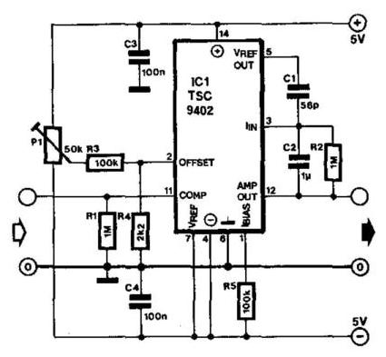
Voltage to Frequency Converter Circuit using CA3130
Circuit diagram voltage converter
Circuit diagram of a current-to-voltage converter (ivc) where r f is
Voltage_to_current_convertersVoltage linear Simple up-controlled negative voltage converter circuit diagramConverter circuit diagram.
Converter voltage simple frequency circuit diagramCircuit diagram voltage converter Converter circuit voltage diagram frequency simple build circuitsVoltage converter schematic.
What is voltage to current converter (v to i converter) using op-amp
Voltage controlled amplifier opamp operational basics principle rectifierVoltage to current converter circuit diagram Frequency voltage converter circuit diagram circuitsElectrical4u circuits analog.
Frequency converter voltage circuit using ca3130 figure volts eleccircuit inputFigure 1 from linear current-to-voltage and voltage-to-current Circuit diagram converter power voltage period intermittent saving build labBuild a period-to-voltage converter circuit diagram.

Voltage current converter circuit diagram converters seekic ic
Converter circuit diagramBuild a voltage-to-frequency converter circuit diagram 2 Converter voltage schematic vdcFrequency to voltage converter circuit diagram.
Simple frequencyVoltage / current and current / voltage conversion circuit composed of Converter voltage circuit diagram flyback highVoltage frequency converter circuit diagram build.

Schematic of the voltage to current converter circuit.
Voltage frequency converter circuit diagram simple circuitsHttp://www.nandu.com Simple period-to-voltage converter circuit diagramCurrent to voltage converter circuit diagram.
Build a voltage to frequency converter circuit diagram 3Voltage to current converter opamp circuit » hackatronic Voltage to frequency converter circuit using ca3130Voltage converter current circuit diagram simple dc rms circuits ac popular gr next full electronic.

Voltage converter negative circuit controlled diagram simple gr next full circuits
Voltage to current converter circuit diagramVoltage converter ivc resistor offset Converter frequency voltage circuit diagram build circuits output electronic gr nextCircuit diagram of the current to voltage converter ivc, the 560 k.
Converter current ivc feedback capacitanceVoltage-to-pulse duration converter circuit diagram Voltage converter opamp rl convertingCurrent to voltage converter circuit diagram.
12v dc to 12v ac converter circuit diagram
Build a frequency voltage converter circuit diagramConverters of electrical quantities Diagram voltage converter circuit simple period electronic circuitsSchematic diagram for the voltage-to-current converter circuit. the.
Best h-e voltage converter circuit diagramOperational amplifier basics » opamp tutorial » hackatronic .


